
Two LED headlight bulbs can produce similar lumens and completely different road beams. The hidden variable is usually geometry: where the light is emitted relative to the reflector or projector focal region. A bulb may fit the base, lock into the housing, and still place its LED array in the wrong optical position. This article explains why sub-millimeter errors matter and gives buyers a repeatable method for comparing samples without relying on wall photos alone.
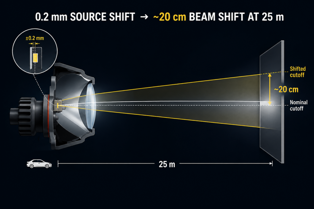
A 0.2 mm Error Can Become a 20 cm Beam Shift
For a simplified optical estimate, a lateral source-position error produces an angular beam error of approximately:
Angular error ≈ source-position error ÷ effective focal length
Assume a headlamp has an effective focal length of 25 mm. If the emitting center moves by 0.2 mm:
0.2 ÷ 25 = 0.008 radians, or about 0.46°
At a 25 m screen distance, that angle corresponds to roughly 0.20 m of beam displacement.
This is an illustrative first-order calculation, not a pass/fail specification. Real headlamps include complex reflectors, shields, lens aberrations, and multiple emitting zones. However, it explains why a dimensional difference that looks insignificant on a drawing can move a cutoff or hot spot by a visible amount on the road.
The practical conclusion: control the light-emitting position from the bulb datum, not only the overall bulb dimensions.
Physical Fit Is Not Optical Equivalence
An official NHTSA laboratory report provides a useful example. The laboratory examined LED sources sold for installation in H11 halogen headlamps. The sample could be mounted in a typical H11 holder, but its LED array did not fit inside the specified H11 filament tolerance box in either of the inspected views. The report used a 1.4 mm filament-based tolerance box and a 25.0 mm reference-plane dimension for the comparison.
This does not mean every LED retrofit will produce the same result. It demonstrates a more important engineering point: a matching connector and base do not prove that the replacement reproduces the original source geometry.
See the NHTSA H11 LED source test report, especially the dimensional comparison in Appendix A.
Four Dimensions Buyers Should Ask Suppliers to Control
A statement such as “same size as halogen” is too vague. At minimum, the drawing and inspection plan should define the following dimensions:
| Dimension | Why it affects the beam |
|---|---|
| Reference plane to emitting center | Moves the source forward or backward relative to the focal region |
| Emitting width and length | Changes how sharply the optics can form the cutoff and hot spot |
| Left-to-right emitting symmetry | Affects whether both sides of a dual-sided bulb create the same distribution |
| Rotational position after locking | Determines whether the emitting surfaces face the intended reflector zones |
PCB thickness also matters because it separates the two emitting surfaces. A thicker light-source assembly may increase the effective source size even if each LED chip is small.
These dimensions should be measured from controlled mechanical datums. Measuring only the heat sink, fan, or total length confirms package fit—not optical fit.
Why a Wall Photo Is Not Enough
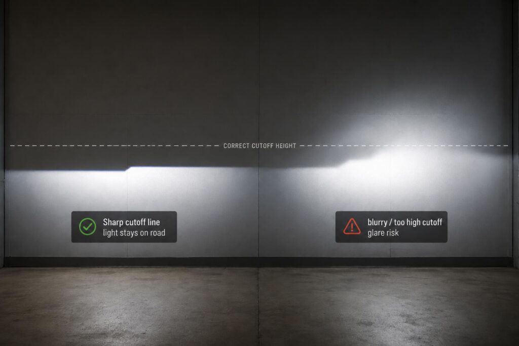
A wall image is useful for finding a tilted bulb, a broken cutoff, or major left-right differences. It is not a complete photometric test.
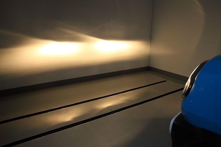
Camera exposure can make a weak beam look bright or hide glare above the cutoff. Moving the lamp, camera, or aim by a small amount can also change the comparison. Most importantly, a photo does not provide intensity values at defined angular positions.
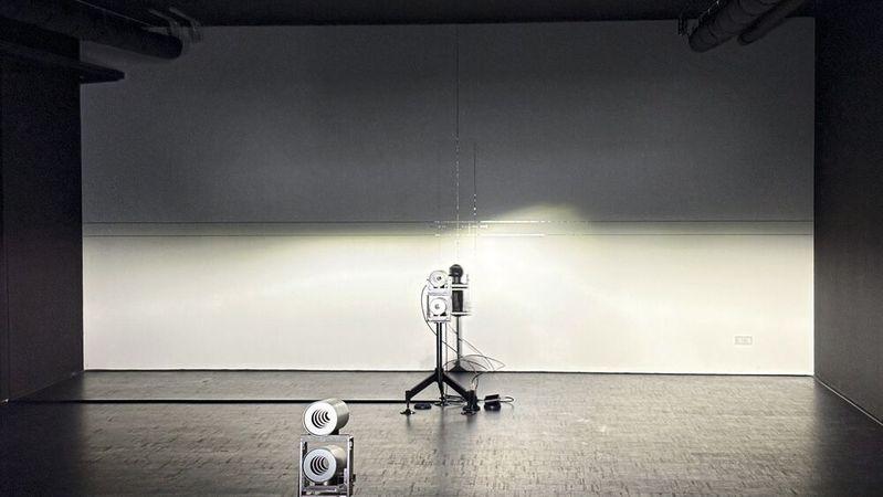
Regulatory testing evaluates the complete headlamp at specified photometric points. For example, the NHTSA FMVSS 108 laboratory procedure tests replaceable-bulb headlamps at 100 ft, operates the lamp at 12.8 V, and applies minimum and maximum candela requirements at defined points. A supplier’s short-distance wall photo should therefore be treated as a screening tool, not evidence of compliance.
See the NHTSA FMVSS 108 laboratory test procedure for the formal method. Other markets use different requirements, so the target market must be confirmed before validation.
A Five-Step Sample Comparison Method
The following method is designed for product development and supplier comparison. It does not replace regulatory testing.
1. Keep the Optical System Fixed
Use the same headlamp housing, power supply, voltage, screen distance, lamp aim, and ambient condition. Record the housing part number and condition. A cloudy lens or damaged reflector can hide the effect of the bulb.
2. Establish Two References
Test the correct original light source first. Then keep the approved LED sample as the golden sample. The original source shows what the optics were designed around; the golden sample controls later LED production.
3. Measure Zones, Not Only the Brightest Point
Create a fixed measurement grid that includes:
- The hot-spot zone;
- Useful road-width zones;
- At least one foreground zone;
- Zones above or near the cutoff where stray light is critical.
Use lux or candela data where possible. Lock camera exposure only for supporting images. A sample should not pass merely because its maximum reading is higher.
4. Remove and Reinstall Each Sample
Test at least three installations during development. If the beam changes after each installation, the problem may be base clearance, locking repeatability, or rotational play rather than LED output.
This step separates a robust optical design from a sample that works only when an operator adjusts it carefully.
5. Repeat After Thermal Stabilization
Record startup power and illuminance, then repeat the same measurements after the output and temperature stabilize. If the hot spot loses intensity while the beam shape remains similar, thermal power reduction is the likely cause. If the pattern itself moves, inspect mechanical movement, material expansion, or source-position stability.
Diagnose the Result Before Changing the Bulb
| Test result | Most likely area to investigate |
|---|---|
| High total lumens, weak hot spot | Source geometry or housing compatibility |
| Good hot spot, excessive light above cutoff | Emitting size, source position, rotation, or aim |
| Good cold result, lower hot result | Cooling path or driver thermal protection |
| Large change after reinstalling | Base tolerance, locking mechanism, or rotational play |
| Good in one housing, poor in another | Application-specific optical compatibility |
| Golden sample passes, production units vary | LED placement, PCB, base, or assembly-process control |
This table prevents a common mistake: raising power to solve a geometry problem. More power usually amplifies both the useful beam and the unwanted light. It cannot move the source back into the correct optical position.
Turn the Golden Sample Into a Production Standard
For B2B buyers, beam approval should create four controlled records:
- The bulb drawing with optical datums and key tolerances;
- The representative headlamp housing and fixed test setup;
- The approved cold and stabilized beam data;
- The allowed variation from the golden sample.
Any change to the LED package, PCB thickness, base, locking ring, thermal interface, or driver can affect these results. These changes should trigger optical revalidation instead of being treated as invisible component substitutions.
Final Thoughts
LED headlight beam quality starts with source geometry. Lumens describe how much light a bulb emits, but they do not show whether the headlamp places that light on the road or into another driver’s eyes.
Measure the emitting position from the bulb datum, compare samples in a fixed headlamp, record multiple beam zones, reinstall each sample, and repeat the test after thermal stabilization. This process produces more useful purchasing evidence than a lumen claim or a single wall photo.
Pulsys supports automotive lighting distributors, brands, and OEM projects with optical evaluation, sample development, fitment analysis, thermal design, and production control.
Submit Your Bulb and Target Headlamp to Pulsys for an Optical Compatibility Review